Servo moters are controlled by sending an electrical pulse stream known as Pulse Width Modulation (PWM). The control wire receives a pulse every 20 milliseconds (a 50Hz frequency).
The width (duration) of this pulse determines the target angle of the shaft:
- 1.0 millisecond pulse: Tells the servo to move to 0 degrees (Far Left).
- 1.5 millisecond pulse: Tells the servo to move to 90 degrees (Neutral Center).
- 2.0 millisecond pulse: Tells the servo to move to 180 degrees (Far Right).
Required Components
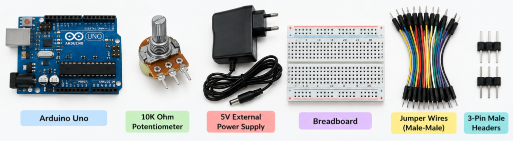
- Microcontroller: Arduino Nano or Uno
- Potentiometer: 10kΩ linear
- Power Source: 5V external power supply or battery pack (Do not power the servo directly from the Arduino 5V pin, as servos draw high current spikes)
- Misc: Breadboard, jumper wires, and 3-pin male headers
Wiring Diagram
- Potentiometer Connections: Connect the left pin to GND, the right pin to Arduino 5V, and the center wiper pin to Arduino Analog pin A0.
- Servo Connections: Connect the servo Ground (Brown/Black wire) to common GND, the VCC (Red wire) to the External 5V Power, and the Signal (Orange/Yellow wire) to Arduino Digital Pin 9.
- Common Ground: Connect the Arduino GND pin to the External Power Supply GND pin to establish a shared reference. [1, 2, 3]
The Arduino Code
#include <Servo.h>

Servo myServo;        // Create a servo object
const int potPin = A0; // Potentiometer connected to analog pin 0
int potValue;         // Variable to read the value from the analog pin
int angle;            // Variable to store the converted angle

void setup() {
  myServo.attach(9);  // Attaches the servo on pin 9 to the servo object
}

void loop() {
  potValue = analogRead(potPin);            // Read potentiometer (0 to 1023)
  angle = map(potValue, 0, 1023, 0, 180);   // Scale it to use it with the servo (0 to 180 degrees)
  myServo.write(angle);                     // Set the servo position
  delay(15);                                // Wait for the servo to get there
}